Definition
Chua's circuit is a simple electronic circuit that exhibits classic chaos theory behavior.
Basics
Chua's circuit
Chua's circuit is a simple electronic circuit that exhibits classic chaos theory behavior. It was introduced in 1983 by Leon O. Chua,
who was a visitor of Waseda University (Japan) at that time (Matsumoto
1984). The ease of construction of the circuit has made it a ubiquitous
real-world example of a chaotic system, leading some to declare it 'a
paradigm for chaos' (Madan 1993).
An autonomous circuit made from standard components (resistors, capacitors, inductors) must satisfy three criteria before it can display chaotic behaviour. It must contain:
- one or more nonlinear elements
- one or more locally active resistors
- three or more energy-storage elements.
Chua's circuit is the simplest electronic circuit meeting these
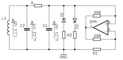
criteria. As shown in the figure, the energy storage elements are two
capacitors (labeled C1 and C2) and an inductance (labeled L1). There is
an active resistor (labeled R), and a nonlinear resistor, shown in the
half-right part of the figure, that is made of the ensemble of five
linear resistors, two diodes and an operational amplifier in the present example.
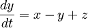
By means of the application of the laws of electromagnetism, the dynamics of Chua's circuit can be accurately modeled by means of a system of three nonlinear ordinary differential equations
in the variables x(t), y(t) and z(t), which give the voltages in the
capacitors C1 and C2, and the intensity of the electrical current in
the inductance L1, respectively. These equations read:
![\frac{dx}{dt}=\alpha [y-x-f(x)]](chuas_circuit_files/ffef870ec8b112fc6dd0bc65c921282d.png)

The function f(x) describes the electrical response of the nonlinear
resistor, and its shape depends on the particular configuration of its
components. The parameters α and β are determined by the particular
values of the circuit components.
A chaotic attractor,
known as "The Double Scroll" because of its shape in the (x,y,z) space,
was first observed in a circuit containing a nonlinear element such
that f(x) was a 3-segment piecewise-linear function (Matsumoto 1985).
The easy experimental implementation of the circuit, combined with
the existence of a simple and accurate theoretical model, makes Chua's
circuit a useful system to study many fundamental and applied issues of
chaos theory. Because of this, it has been object of much study, and appears widely referenced in the literature.
Articles
- Matsumoto, T. "A Chaotic Attractor from Chuas's Circuit." IEEE Trans. CAS 31, 1055-1058, 1984.
- Matsumoto, T., Chua, L. O., and Komuro, M. "The Double Scroll." IEEE Trans. CAS 32, 798-818, 1985.
Books
- Chaos synchronization in Chua's circuit, Leon O Chua,
Berkeley : Electronics Research Laboratory, College of
Engineering, University of California, [1992], OCLC: 44107698
- Chua's circuit: a paradigm for chaos, R N Madan, River Edge, N.J., World Scientific, 1993
Source: Wikipedia (All text is available under the terms of the GNU Free Documentation License and Creative Commons Attribution-ShareAlike License.)
|


